
Today, all day, I worked on completing the analysis of the varied sodium DNA samples and create a PowerPoint and I am almost finished!!!
No comments


Today, all day, I worked on completing the analysis of the varied sodium DNA samples and create a PowerPoint and I am almost finished!!!
Today:
 |
| Attached camera with rigged power supply. |
Today, I recreated the sodium-varied samples at 20x dilution and ran them through the ICP twice. Mistake time: I tried to open up chrome once I began the second run to send myself the first set of data and apparently that is a horrible idea because the computer freaked out and shut down 🙁
Once I got the computer to be alive again, I ran the data for the second time. This afternoon, I started work on the data from the four runs of the samples. Tomorrow I will fix the graphs, clean up the excel file and create a PowerPoint to share with our collaborators including full explanations of the method, error propagation and detailed explanation of each graph.
Today with the help of Dr. Good we managed to get the LED collimated. Although the setup is slightly different now in its attachment to the kinematic mount, it still functions the same.
 |
| The setup with the mounted LED in place. |
 |
| The Beam of Reasonable Collimation |
I continued my work with porting the code for all of the stepper motors. I also added a table which can save values to screen of the stepper motor coordinates.
I began my day by trying to figure out why the .flx files generate errors, even when they are being used for the same motor control board as in the code. What I found was that a separate motor control board was being used for the other stepper motors. So, my next task which I already started today successfully is to port the code for these stepper motors for use with our motor control board. To do this, I took the code that already works for our stepper motors that will move the xy table, and began to allow it to move the other stepper motors. I managed to successfully do this with the stepper motor for the objective.
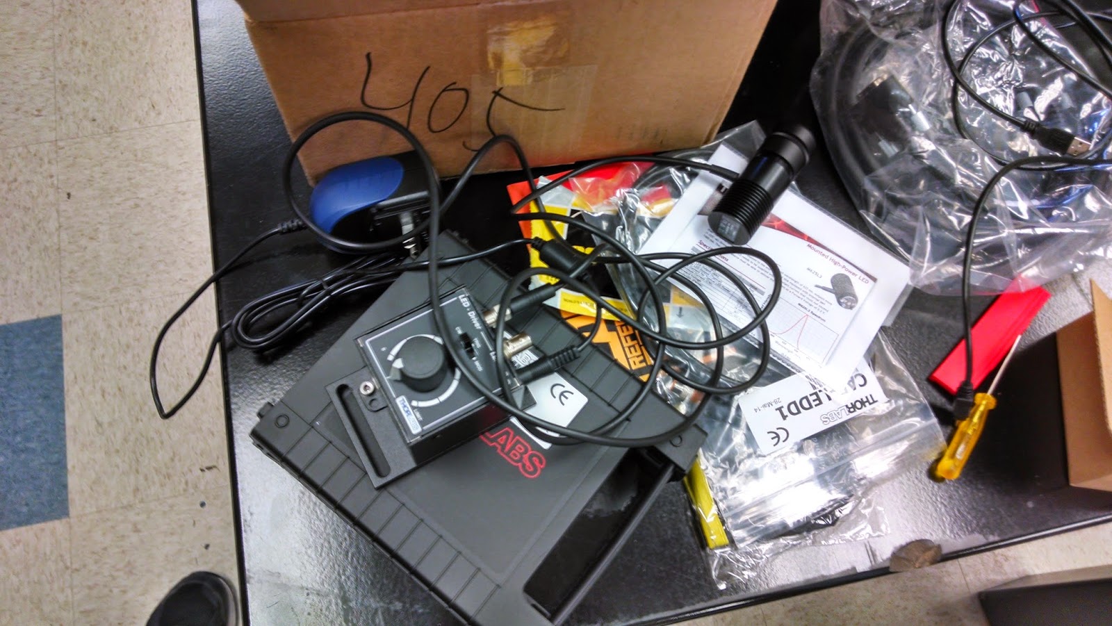 |
| The LED with the attached current driver. Trust me, it works. |
Towards the end of the day Professor Andresen began to show me how to use the different machines in the workshop. We managed to machine one of the four posts that will hold up the rest of the tweezers set up. So now, the lab looks like this:
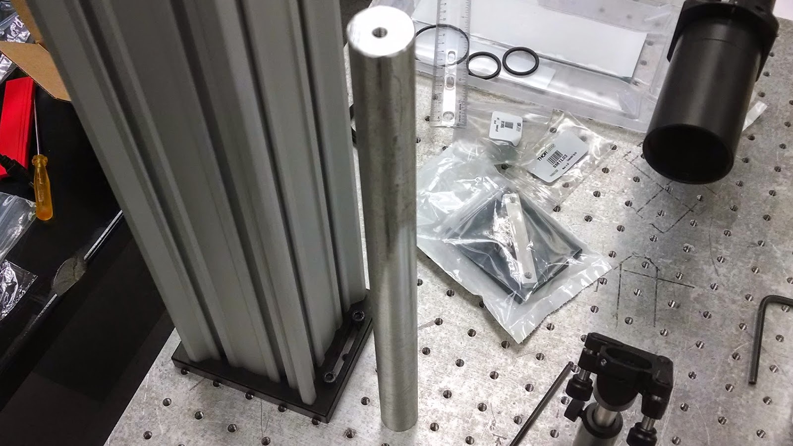 |
| The post that Professor Andresen machined. 1/4″ 20 tapped holes on both ends. |
 |
| How the floating table looks now. It’s all coming together. |
I ran the six calibration solutions on the ICP and got reasonable results so I continued to run the calibrations with the first sample set I made yesterday. This data should follow a similar trend-line to the first sample run because the only difference was the concentration of the samples. However, the buffer solution had a much higher sodium concentration, by a factor of ten, causing the relative sodium in each sample to be much lower as seen in the graph below. Tomorrow, I hope to find the cause of this inconsistency and possibly make new samples at the same dilution.
 |
| Figure shows the difference in the sodium concentration for each of the samples and the common buffer used for all samples. Because the measured level of sodium in the buffer was so high, the first few samples to show a concentration less than zero. |
The rails came in yesterday, allowing us to finalize our positioning of objects on the bread board to estimate the size of items that we will machine. For the LED, we will be placing an order for a current driver and power supply.

Today, after discussing the goals of the week as a group, I began figuring out how to structure the next part of the experiment. I decided, with much help from Prof. Andresen, to run the first set of samples that has varying sodium concentrations at a 20x dilution. I created six new calibration solutions with different levels of sodium, cobalt and phosphorus than the last calibration set. I plan on running the new calibration set this afternoon and I will begin running the DNA samples tomorrow.
Today, we figured out how to connect the kinematic mount to the posts. Turns out, those posts have quite an ingenious design.
Today I began setting up the different optical components that just recently arrived for a mock up as to how we might want to build things. As of right now, I have the lens tube holder and mirror kinematic holder set up in a decent fashion.
 |
| Side view of the lens tube setup with the kinematic mount for the mirror. The whole setup can be raised or lowered as needed. |
One of the first problems that I ran into with the optomechanical components was with our larger kinematic mount. This larger mount will be used to hold the LED with the collimator attached to it.
The problem that I found was with the screws provided for the kinematic mount. The problem is that the screw size is too small for our optical posts; the stainless steel rods you see in the pictures to the left. To complicate things, it turns out that the large kinematic mount is not threaded, so the optical posts can’t be screwed into the kinematic mounts either.
 |
| Ideally, this should be enough space for the rest of the tweezers setup to go above the 45 degree mirror. |
 |
| View of the kinematic mount. You can see inside the mounting holes that the hole size changes. |
 |
| Alternative view of the kinematic mount. There is no threading inside of the holes. |
Another issue that I ran into today was with the CCD camera. Unfortunately, we didn’t order a cable for the camera yet. This needs to be done. The problem is, we might end up needing a CameraLink cable, and a frame grabber control board in order to capture images from the camera. This could be costly.
 |
| Closeup of the LED |
 |
| The nifty case that the LED came in with the specs sheet. High-tier. |
Thankfully, the strangeness of these problems that I’m dealing with was mitigated by some quality Lab Swag.
