Week Four: Wednesday

Today with the help of Dr. Good we managed to get the LED collimated. Although the setup is slightly different now in its attachment to the kinematic mount, it still functions the same.

The setup with the mounted LED in place. 

The Beam of Reasonable Collimation

I continued my work with porting the code for all of the stepper motors. I also added a table which can save values to screen of the stepper motor coordinates.

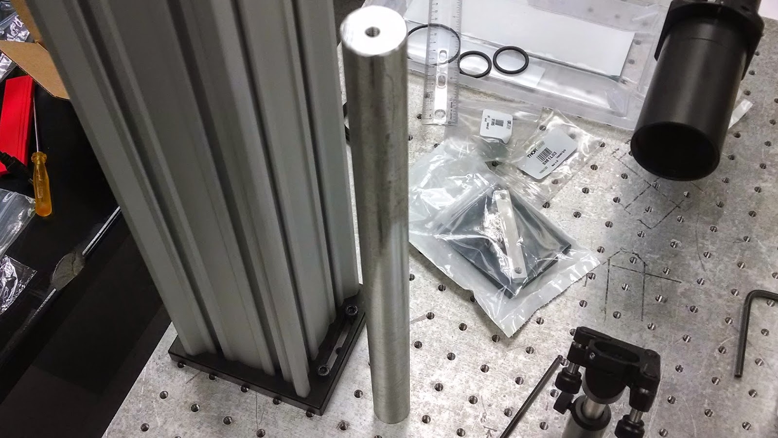
Lastly, Professor Andresen managed to machine one more post bringing our total to two.

Week Four: Tuesday

I began my day by trying to figure out why the .flx files generate errors, even when they are being used for the same motor control board as in the code. What I found was that a separate motor control board was being used for the other stepper motors. So, my next task which I already started today successfully is to port the code for these stepper motors for use with our motor control board. To do this, I took the code that already works for our stepper motors that will move the xy table, and began to allow it to move the other stepper motors. I managed to successfully do this with the stepper motor for the objective. 

The current driver and power supply for the LED arrived today, allowing us to play with the LED for a little bit of fun. Here’s the mess it’s in now:

The LED with the attached current driver. Trust me, it works.

Towards the end of the day Professor Andresen began to show me how to use the different machines in the workshop. We managed to machine one of the four posts that will hold up the rest of the tweezers set up. So now, the lab looks like this:

The post that Professor Andresen machined. 1/4″ 20 tapped holes on both ends.

How the floating table looks now. It’s all coming together. 


Week Four: Tuesday

I ran the six calibration solutions on the ICP and got reasonable results so I continued to run the calibrations with the first sample set I made yesterday. This data should follow a similar trend-line to the first sample run because the only difference was the concentration of the samples. However, the buffer solution had a much higher sodium concentration, by a factor of ten, causing the relative sodium in each sample to be much lower as seen in the graph below. Tomorrow, I hope to find the cause of this inconsistency and possibly make new samples at the same dilution. 

Figure shows the difference in the sodium concentration for each of the samples and the common buffer used for all samples. Because the measured level of sodium in the buffer was so high, the first few samples to show a concentration less than zero.


Week Four: Monday

The rails came in yesterday, allowing us to finalize our positioning of objects on the bread board to estimate the size of items that we will machine. For the LED, we will be placing an order for a current driver and power supply.

In terms of the code, I found that the cursor keys work for controlling the stepper motor. The up/down keys correspond to the x stepper motor, while the y corresponds to the left/right keys. These work through relative moves, but can be switched to absolute moves. All of this was done in the top level of the program. 
At the top level of the code, I added a little bit of code to show the users what coordinates they were at as they moved the stepper motors. We can add on to this code at any time in order to display more useful motor coordinates to the user. 

Week Four: Monday

Today, after discussing the goals of the week as a group, I began figuring out how to structure the next part of the experiment. I decided, with much help from Prof. Andresen, to run the first set of samples that has varying sodium concentrations at a 20x dilution. I created six new calibration solutions with different levels of sodium, cobalt and phosphorus than the last calibration set. I plan on running the new calibration set this afternoon and I will begin running the DNA samples tomorrow.

Week 3: THURSDAY

Today, we figured out how to connect the kinematic mount to the posts. Turns out, those posts have quite an ingenious design. 

More importantly, however, we managed to get the .flx files somewhat working. They exist now, although they run with errors. It doesn’t seem to affect the final read out of the code however. This is an important development, as it opens up more of the code to work on. 
The most important thing that was accomplished today was the figuring out the units of one rotation of the motor in SimpleMove.vi. This is good, because just a little later I figured out how to modify the number of units in one rotation. This is exciting because it means we can modify these units to whatever we want.

Week 3: WEDNESDAY; the build begins…

Today I began setting up the different optical components that just recently arrived for a mock up as to how we might want to build things. As of right now, I have the lens tube holder and mirror kinematic holder set up in a decent fashion. 

Side view of the lens tube setup with the kinematic mount
for the mirror. The whole setup can be raised or lowered as
needed.

 One of the first problems that I ran into with the optomechanical components was with our larger kinematic mount. This larger mount will be used to hold the LED with the collimator attached to it.

The problem that I found was with the screws provided for the kinematic mount. The problem is that the screw size is too small for our optical posts; the stainless steel rods you see in the pictures to the left. To complicate things, it turns out that the large kinematic mount is not threaded, so the optical posts can’t be screwed into the kinematic mounts either.

Ideally, this should be enough space for the rest of the
tweezers setup to go above the 45 degree mirror.
Ideally, you could just drill a hole into the kinematic mount to run a screw through it and into the stainless steel post. The thread count for the stainless steel post is unknown however, which will make it difficult to find something to attach it with. I believe that Thorlabs does this with their threading in order to make it so that you have to purchase their products.
It's just like robotics all over again! So many parts and nothing fits right.
View of the kinematic mount. You can see inside the mounting holes that the hole size changes.

Alternative view of the kinematic mount. There is no threading inside of the holes.

Another issue that I ran into today was with the CCD camera. Unfortunately, we didn’t order a cable for the camera yet. This needs to be done. The problem is, we might end up needing a CameraLink cable, and a frame grabber control board in order to capture images from the camera. This could be costly.

Finally, I began to look at the high-powered LED that we received from Thorlabs. According to the included specs sheet, we’ll need a power supply that can deliver current at a Forward Voltage of 2.2 V. This is quite strange. We also probably don’t have anything that can provide that. 
Click to zoom to see the LED itself.
Closeup of the LED

The nifty case that the LED came in with the specs sheet. High-tier.

Thankfully, the strangeness of these problems that I’m dealing with was mitigated by some quality Lab Swag.

That bonus pack on the right just arrived today, because another package from Thorlabs came in. In this case it was nice that not everything was shipped at once.

Ithaca Waterfalls!

After four days of running samples for 16 hours each day, we finished our BioSAXS experiments. But before we left, we went to see several of the amazing waterfalls in Ithaca. 

Path leading up to the largest falls. Unfortunately the path was closed further up because of construction, so we had to circle back and follow another path to the waterfalls. 
WATERFALL!!
Prof. Andresen attempting to take a panoramic view of the falls. 


Week Three: TUESDAY

I started the day off by figuring out once again what the initial motor position would be if I connected everything up to the computer and ran the motor control code. Once again, I found that it was initialized to -16,777,216. This number must have some meaning, but I am not sure what.

Following this, I attempted to figure out how to do a little programming challenge to see if we could make the motors do what we want them to in the long run, or figure out if the existing code we have can accomplish this. The task is as follows:
1) Tell the motor to rotate 3.5 turns and stop.
2) Move back 1.2 turns and stop.
3) Report the position as 2.3
4) Save this position so that when the program is closed and reopened it still recognizes that the motor is at 2.3, ceteris paribus.

As it turns out, this is a bit more difficult than it would seem. The reason for new positions in the motor becoming zero each time the control board is unplugged as opposed to the program being closed and reopened is because the motor position is stored in the control board’s memory, not the program’s.

So how difficult is it to create a vi to do what was described above? Not very, but you need to have the right tools. Tasks 1) through 3) can easily be accomplished with the base code that I’ve been working with, but the unit “turns” would have to be figured out empirically. This is not optimal, so I set out to figure out what the units were, and more importantly, how this motor code works in the scheme of the whole program.

It turns out that the units, speed, and voltage of the motors can all be calibrated in a nice little calib.ini file. This file is then called by a CalibConstants.vi which appears everywhere in the overall tweezers.vi code structure. This CalibConstants.vi should be able to figure out the units and normalize instructions from turns to what the base code I was using earlier uses for units.

CalibConstants.vi is unfortunately not run-able because there are two important files missing: Reset Position.flx and Read Position.flx. The observant reader would note that these file endings are different for every other LabVIEW file that I’ve discussed so far. That’s because, (after doing a little bit of research) these files are related to the NI-Motion set of *stuff*. .flx are Flex Motion files, used by the NI-Motion driver. These .flx files appear several times throughout the tweezers.vi and are most of the missing files in all of the code.

With the inclusion of these two .flx files, CalibConstants.vi should be run-able, and by extension, simplemove.vi, which is the overhead code for the base motor code I’ve been using, which should mean that the programming task I outlined above is entirely executable by the existing code we have. Also, since much of the tweezers.vi code has CalibConstants.vi throughout it, more of that code will be run-able too. This is exciting since our camera and other optics equipment just arrived today.

So what’s the bottom line? Either we rewrite the code or get this NI-Motion driver which should contain the .flx libraries. I did manage to comment out sections of the CalibConstants.vi and SimpleMove.vi that referred to the .flx files we don’t have. I managed to get both running, but since I commented critical sections out, the code was stuck in an infinite while loop and I was unable to proceed further.

CHESS: Second half of BioSAXS

Yesterday, after looking over the data from overnight, Prof. Andresen and I began running more samples. Instead of varying the salt concentration (the amount of K in each sample for dilutions of 1x, 2x, and 4x) we began changing the contents of each sample and diluting that. The samples were separated into the categories of blue and red and each had 6 types of samples. The first three were tetramers and the last three were dodecamers. The first in each series was simply the nucleosomes in solution of TEK10, the second included globular H1 protein, and the last included globular H5 protein. For these samples, we did not use any TEK but instead had a buffer of 1mM Mg. This could change much about how the nucleosomes interact because of the change from a +1 ion to a +2 ion in the solution. Because tetramers and dodecamers are more prone to aggregation, we began cleaning the sample cell after each sample much more thoroughly. We washed the buffer solution through the cell twice after running the sample and then washed the water and alcohol through twice as much than on Saturday. On Sunday, we were able to run all of the Red series, a trimer and a large portion of the Blue series. Our other group finished that series and began to run their own samples of proteins. 
Today, we ran the gold samples that were given to us by Prof. Thompson for his experiments. Because the composition of the gold samples was so different than the nucleosome arrays, our sample cell was wrecked and Prof. Andresen had to insert a new cell and reconfigure the alignment. While he was doing this, I attended a thesis defense on the ion interactions with single and double stranded DNA measured using solution x-ray scattering.  This talk included several biophysical techniques that we discussed in physics 246 this past spring such as SAXS (obviously), spFRET and molecular dynamics. The presenter also used data obtained from Gettysburg’s ICP-AES that Prof. Andresen ran. To finish off the day, we are going to run the R series with a 2x dilution for the different levels of TEK (50, 100 and 200) including double the buffer between samples (the TEK of the previous and the TEK of the next). Hopefully we will get through most of the series before we switch off at midnight.